









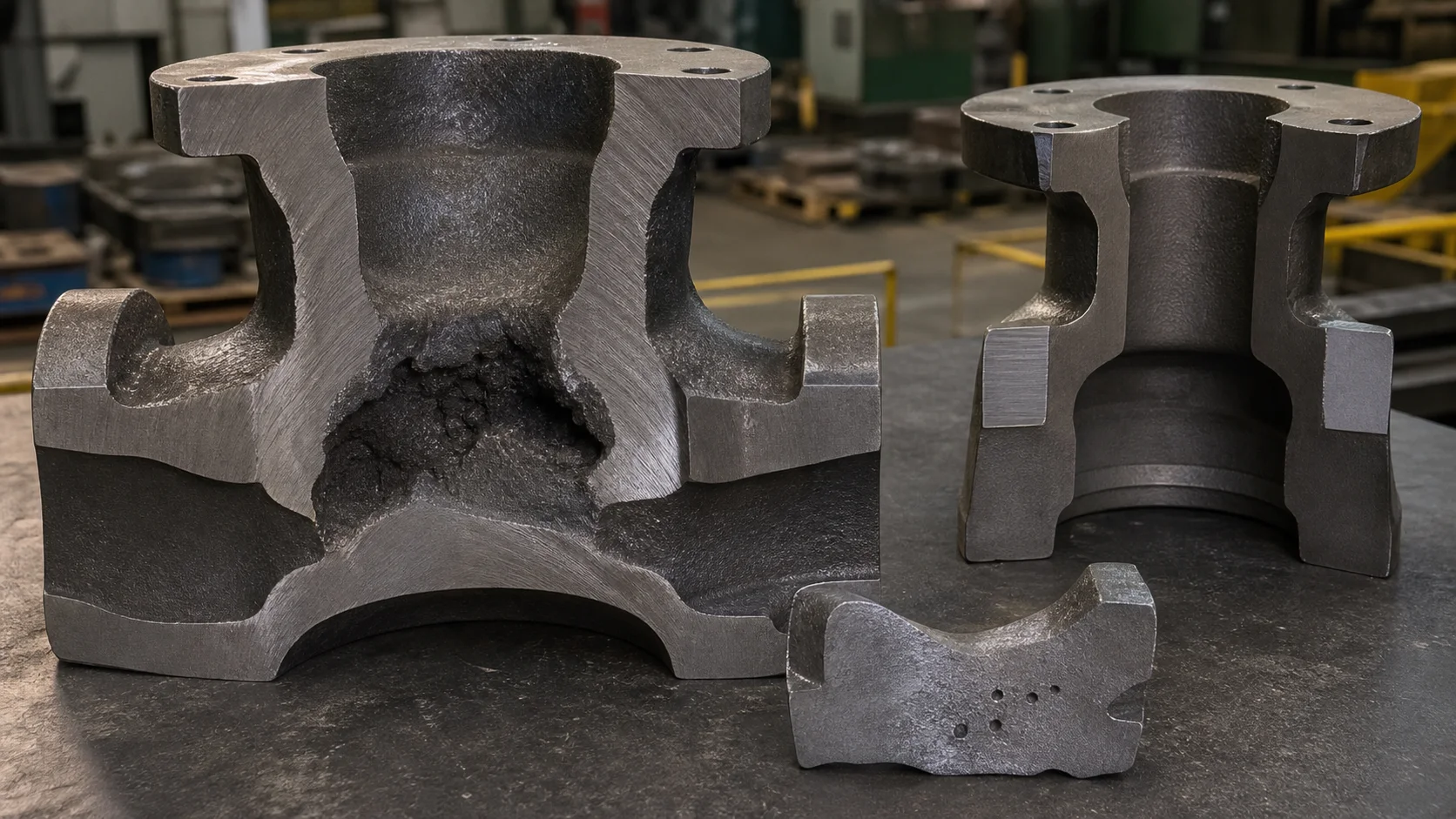
When holes appear on the surface of a casting or internal voids are found after machining, they are often collectively referred to as "sand holes" on site. However, the formation mechanisms of shrinkage cavities, shrinkage porosity, gas porosity, sand inclusions, and cracks are completely different. If the diagnosis is wrong, the direction of rework and prevention will also be wrong.
In conclusion: smooth, nearly circular cavities are more likely related to gas; irregularly shaped cavities with rough inner walls located in thick, hot spots are more likely to be shrinkage cavities or shrinkage porosity; defects containing non-metallic materials may be slag inclusions or sand inclusions; long, thin openings with a propagating direction should raise suspicion of cracks. The final conclusion cannot rely solely on visual inspection; it should be based on the defect location, fracture morphology, process records, and non-destructive testing.
Five common typesCasting defectsHow to distinguish them?
| defect | Common morphology | Frequent locations | Main risks |
|---|---|---|---|
| shrinkage cavity | Irregularly concentrated cavities with relatively rough inner walls | Thick cross-sections, hot spots, and insufficient feeding | Reducing the effective load-bearing cross section may cause leakage in pressure-bearing components. |
| Shrinkage | Fine, dispersed or sponge-like pores | Final solidification zone, thickness-thin boundary | Post-processing exposure, reduced airtightness and fatigue performance |
| pores | Nearly circular, with relatively smooth inner walls | Surface, localized accumulation, or the entire cross-section | Affects appearance, processing and sealing performance |
| Sand holes/fragment inclusions | The pores may contain sand particles, oxides, or non-metallic inclusions. | Areas with insufficient sand flushing, slag removal, and filtration | Stress concentration occurs, contaminating the processed surface. |
| crack | Slender, sharp, and directional | Insufficient fillet radius, abrupt changes in thickness, and areas where contraction is hindered. | This defect could continue to expand and is considered a high-risk defect. |
Why are shrinkage cavities and cracks prone to appear at the junction of thick and thin layers?
Thick sections cool slowly, while thin-walled sections solidify first. If the last solidified zone does not receive sufficient molten metal replenishment, shrinkage cavities or porosity may form. On the other hand, hindered structural shrinkage, excessively small fillet radius, or excessive temperature differences between different cross-sections can increase the risk of hot cracking and residual stress.
- Try to keep the wall thickness uniform and make the transition between thicknesses smooth.
- Place risers, gating systems, and chills where solidification control is truly necessary;
- The process is designed by considering the alloy shrinkage characteristics, pouring temperature, and mold conditions.
- Critical machining surfaces and pressure-bearing boundaries should be marked during the drawing review stage.
After processing, holes or pressure leaks were found.It is possibleSend defect photos, drawings, and location via WeChatSpecify the material, wall thickness, quantity, and usage requirements to determine whether it is suitable for repair or re-optimization of the casting plan.
Porosity is not always caused by pouring temperature.
Porosity can originate from gas in the molten metal, residual moisture in the mold shell or core, insufficient dewaxing and baking, gas entrapment during pouring, poor venting, or may be related to reactive gases. Simply adjusting the pouring temperature without inspecting the melting, mold shell, and gating system often fails to address the root cause.
Which detection methods can find these defects?
| Detection methods | Suitable for discovery | Limitations |
|---|---|---|
| Visual inspection and dimensional check | Obvious surface defects, deformation, and missing material | Internal quality cannot be reliably determined |
| Penetrant Testing (PT) | Surface-opening cracks and pores in non-porous materials | Unable to detect closed internal defects |
| Magnetic Particle Inspection MT | Surface and near-surface defects in ferromagnetic materials | Austenitic stainless steel is generally not suitable |
| Ultrasonic testing UT | Abnormal internal reflection of cast steel parts of a certain thickness | Assessing coarse-grained and complex austenitic structures is more difficult. |
| Radiographic Testing (RT) | Volumetric porosity, shrinkage cavities, and inclusions | High requirements for cost, directionality, and safety management. |
Can defects be repaired directly by welding?
Repairing before assessment is not advisable. First, confirm the material standards, defect type, size, location, and whether welding repair is permissible for the product. Stricter requirements are typically imposed on pressure zones, near sealing surfaces, fatigue stress areas, and areas where welding repair is prohibited by the customer. Even when repair is permitted, qualified welding procedures should be used, with preheating, post-weld treatment, and re-inspection performed as required.
How can we reduce disputes over defects in procurement drawings?
- Mark the pressure-bearing boundary, critical stress area, sealing surface, and machined surface;
- Specify the areas where welding is permitted or prohibited;
- Specify the location, proportion, and acceptance level for PT, MT, UT, or RT;
- Agreed upon the handling method for defects discovered after processing;
- Clearly define the requirements for sample confirmation, first article report, and batch traceability.
Frequently Asked Questions
Are small holes that appear after processing considered air holes?
Not necessarily. Shrinkage, inclusions, and porosity can all cause pores after processing. The location, morphology, and testing should be considered for diagnosis.
Does the absence of surface defects necessarily mean that the internal structure is up to standard?
No. Internal shrinkage cavities, shrinkage porosity, and inclusions may only be exposed after machining or X-ray/ultrasonic inspection.
Is a stricter defect rating always better?
Not all areas need to be classified at the same level. Critical zones should be defined based on pressure, stress, fatigue, and processing risks to avoid unnecessary costs.
From defect assessment to process evaluation
Haijin Stainless Steel can assess wall thickness, hot spots, machining allowances, and testing requirements based on stainless steel, carbon steel, and alloy steel casting drawings. (See attached image.)Quality control和Custom non-standard castings, or enterProcurement ContactCommunicate existing issues.
This document is for defect communication purposes only and does not replace formal testing and failure analysis. Defect acceptance should be based on drawings, product standards, contracts, and confirmed acceptance levels.
Relevant technical information and product examples
Continue to assess whether the materials, workmanship, and actual parts are suitable for your procurement needs.
- Process ComparisonHow to choose between silica sol process and water glass process?→
- Process ComparisonWhat are the differences between precision casting and powder metallurgy?→
- Quality requirementsPrecision casting surface roughness and polishing treatment→
- Product ExamplesCNC machining of industrial and mechanical parts casting→
Manufacturing process evaluation
We need to determine which manufacturing process is suitable for this part.
Please provide the structure, material, quantity, key dimensions, and surface requirements. We will conduct an evaluation based on precision casting, post-processing, CNC machining, and inspection.
- Assess wall thickness, fillet radius, and molding risks.
- Confirm casting allowance and post-machining location
- Select process based on quantity, quality and delivery time.
 WhatsApp: +86 158 9600 2001Scan the QR code or open WhatsApp to chat


