











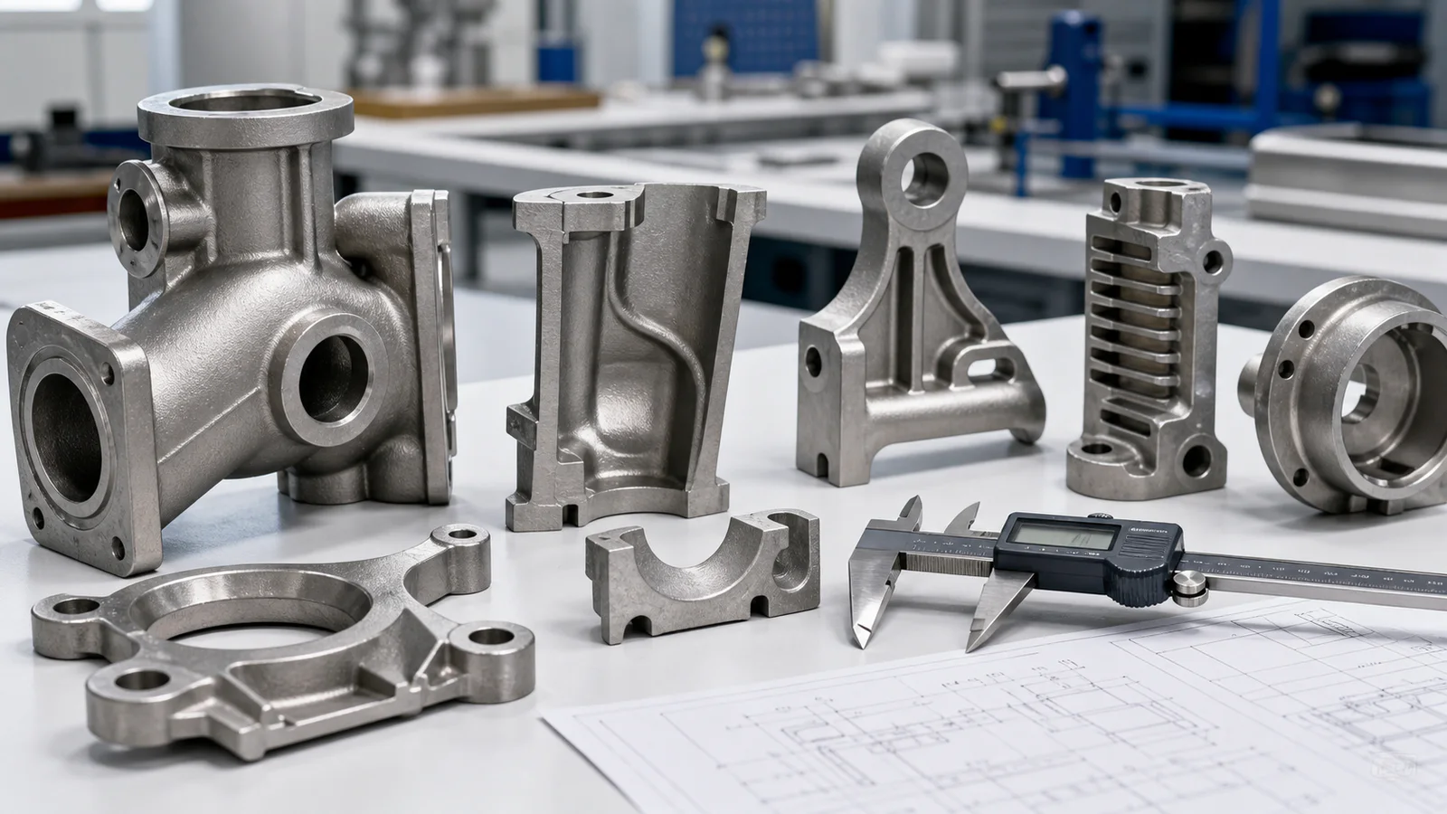
Draft angle of castingWhat is the typical angle? This question cannot be answered simply with "1°" or "2°". The angle depends on the draft length, inner and outer surfaces, molding method, mold structure, and surface requirements. For silica sol...Investment CastingThe draft angle is mainly used to facilitate the smooth removal of the wax pattern from the metal mold; insufficient draft angle can easily cause tearing, deformation or whitening, while excessive draft angle will increase weight, change assembly space and machining allowance.
National StandardsGB/T 42124.3-2025The formal terminology used is“"Draft angle"”Engineers often refer to this as draft angle, demolding angle, or casting angle. This article compiles the investment casting data from this standard into searchable and translatable text tables.
Draft angle和Internal draft angleWhat's the difference?
- Draft angle of outer mold:It is placed on the outer surface of the casting or wax pattern, which usually provides good release space during demolding;
- Internal draft angle:Locations such as holes, cavities, and inner walls that tightly enclose the mold core are usually more sensitive to demolding resistance.
- Demolding length:Effective height along the demolding direction. For the same linear draft angle value, the shorter the demolding length, the larger the corresponding angle.
- Parting and demolding direction:When the parting surface or core-pulling direction of the same part is changed, the surface that requires an angle will also change.
Therefore, the internal cavity angle is not simply a direct copy of the external wall angle. In the new standard's investment casting tables, the internal draft angle for DB grade is usually greater than the external draft angle, precisely to reflect the fact that the internal surface is more difficult to demold.
GB/T 42124.3-2025Investment casting draft angle表
The following table is compiled according to Table 6 of GB/T 42124.3-2025. The values outside the parentheses are angles, and the values inside the parentheses are the linear draft angle values corresponding to the nominal size range, in millimeters.
| Demolding length/mm | DA outer mold | DA internal molding | DB External Mold | DB Inner Mold |
|---|---|---|---|---|
| ≤4 | 5.7° (0.2) | 5.7° (0.2) | 5.7° (0.2) | 8.5° (0.3) |
| >4~6.3 | 2.2° (0.2) | 2.2° (0.2) | 2.2° (0.2) | 3.3° (0.3) |
| >6.3~10 | 1.4° (0.2) | 1.4° (0.2) | 1.4° (0.2) | 2.8° (0.4) |
| >10~16 | 0.9° (0.2) | 0.9° (0.2) | 0.9° (0.2) | 1.8° (0.4) |
| >16~25 | 0.8° (0.3) | 0.8° (0.3) | 0.8° (0.3) | 1.4° (0.5) |
| >25~40 | 0.5° (0.3) | 0.5° (0.3) | 0.5° (0.3) | 1.1° (0.6) |
| >40~63 | 0.5° (0.4) | 0.5° (0.4) | 0.5° (0.4) | 0.8° (0.7) |
| >63~100 | 0.3° (0.4) | 0.3° (0.4) | 0.3° (0.4) | 0.6° (0.8) |
| >100~160 | 0.2° (0.5) | 0.2° (0.5) | 0.2° (0.5) | 0.4° (0.9) |
| >160~250 | 0.2° (0.6) | 0.2° (0.6) | 0.2° (0.6) | 0.3° (1.0) |
| >250~400 | 0.1° (0.7) | 0.1° (0.7) | 0.1° (0.7) | 0.2° (1.2) |
| >400~630 | 0.1° (0.8) | 0.1° (0.8) | 0.1° (0.8) | 0.2° (1.5) |
The table cannot be used directly without the mold scheme.Actual design also requires confirmation of DA or DB grade, parting line, draft direction, ejection method, surface texture, mold wear, and wax pattern stiffness. Particularly complex cavities may require sliders, movable inserts, soluble cores, or modular combinations, rather than continuing to increase the draft angle.
Why is the angle larger for shorter dimensions?
The draft angle can be expressed in angles or as the linear dimensional difference between the two ends of the draft length. For a very short draft height, even if the difference between the two ends is only 0.2 mm, it may be equivalent to several degrees when converted to angles. As the draft length increases, the angles corresponding to the same or similar linear differences will become significantly smaller.
This is why drawing reviews cannot only focus on "how many degrees". Purchasing and engineering personnel also need to confirm which surface the angle is applied to, along which direction the measurement is taken, and whether the added material falls on the large end or the small end.
What do TP and TM mean?
GB/T 42124.3-2025 uses TP (Taper Plus) and TM (Taper Minus) to distinguish the direction of slope relative to the nominal model:
- TP, positive draft angle:This is generally understood as adding a material forming slope to the nominal model;
- TM, negative draft angle:This is generally understood as reducing the material forming slope from one side of the nominal model.
The standard stipulates that, unless otherwise specified, the positive draft angle TP is used by default; for elements with maximum solidity requirements, the positive draft angle is not applicable, and the negative draft angle TM should be used instead. Drawings should not only show an angle without specifying the direction; otherwise, the mold manufacturer and the purchaser may have different interpretations of the finished product boundary.
Is it possible to achieve zero draft angle in precision casting?
Local zero slope is not absolutely impossible, but it requires specific evaluation and cannot be used as a default requirement for all surfaces. Possible solutions include:
- Arrange the zero-slope surface at the parting line;
- Use sliders, angled tops, or movable inserts;
- The inner cavity is formed using a soluble wax core or a ceramic core;
- Make wax models separately and then assemble them;
- Allowance is reserved for the functional surfaces, and straight walls are obtained by CNC machining after casting.
These solutions increase mold complexity, wax pattern seams, deformation control, and production cycle costs. If zero draft angle is not functionally necessary, appropriately relaxing it is usually more conducive to stable mass production.
Which structures require more caution than standard tables?
Deep and narrow inner cavity
The wax pattern will tightly wrap around the long core, resulting in a longer friction stroke. In addition to the angle, it is also necessary to check the venting, filling, ejection force, and core strength.
The surface has text, serrations, or textures.
Texture height increases actual demolding resistance. Text sidewalls, knurling, and fine teeth may require additional draft angles or changes to the parting line.
Thin-walled and long cantilever structures
Even if the surface of a wax pattern is not scratched during demolding, it may still bend due to the ejection force. The position of the ejector pins, support, cooling time, and removal method should be considered simultaneously.
Mating surfaces requiring CNC machining
Draft angle will change the distribution of blank allowance. If the sealing surface, orifice, or mating boundary is subsequently machined, the draft angle should be adjusted accordingly.Machining allowanceLet's check them together.
Five common draft angle problems on drawings
- It only says "draft angle 1°", without indicating the demolding direction;
- The same angle was used for both the inner and outer walls, but the tightness of the inner cavity was not assessed.
- The 3D model already has a slope, but the 2D drawing requires an additional slope.
- The key assembly dimensions are not specified as being accepted based on the large end, small end, or theoretical intersection line.
- In pursuit of zero angle, a more complex slider was added, but the quantity purchased was insufficient to offset the mold cost.
When submitting an inquiry, it is best to provide a product baseline model without draft angles, a model with manufacturing draft angles, or clearly defined two-dimensional annotations, and indicate which document takes precedence. For older drawings, the referenced document should also be verified.GB/T 42124.3-2025 is still the replacement of GB/T 6414-2017.。
How can we conduct a manufacturability review for mold making before submitting a quote?
- Determine the product assembly boundaries and functional surfaces that cannot be changed;
- Determine the main draft direction, parting surface, and necessary lateral core pulling;
- Distinguish between outer surfaces, inner surfaces, and surfaces to be processed later;
- Inspect deep cavities, undercuts, lettering, tooth profiles, thin walls, and ejection positions;
- Confirm whether the slope should be TP or TM, and which end the dimensions should be used for acceptance.
- The final solution is determined by considering batch size, mold life, and mold repair method.
Does the drawing show a deep cavity, straight walls, or inverted design?It is possibleSend STEP model and 2D drawings via WeChatHaijin can be combinedMinimum wall thickness, fillet and slot designFirst, a precision casting manufacturability assessment is conducted for mold parting and CNC machining surfaces.
Frequently Asked Questions
What is the typical draft angle for castings?
Fixed values cannot be given directly without considering the mold length and casting method. Investment casting should be determined in conjunction with Table 6 of GB/T 42124.3-2025, the inner and outer surfaces, the DA/DB grade, and the actual mold structure.
Why is the draft angle of the inner hole usually larger?
After the wax pattern cools, it may tightly encase the mold core, increasing the risk of demolding friction and deformation on the inner surface. Therefore, the inner draft angle of the DB grade in the standard is usually greater than the outer draft angle.
Is the draft angle included in the dimensional tolerances of the casting?
These cannot be simply lumped together. Surfaces with draft angles also involve nominal model, TP/TM orientation, and tolerance area. The new standard also clarifies that general shape and orientation tolerances are not directly applicable to parts with draft angles and should be specified separately when necessary.
Why is draft casting still necessary when precision casting uses the lost-wax casting process?
The wax pattern will eventually be removed, but it must initially be taken out of the metal wax mold. The draft angle serves the purpose of wax pattern demolding, surface protection, and dimensional stability, not the demolding of the ceramic shell from the metal casting.
Sources and Disclaimers
The draft angle data for investment casting in this article are compiled based on Table 6 of GB/T 42124.3-2025 for ease of drawing communication and preliminary design review. This data does not replace the official standard text, customer drawings, or documents confirmed by both the supplier and the customer. Before formal production, the valid version of the standard, all clauses, and the mold design should be verified.
- National Standards Public Service Platform: GB/T 42124.3-2025
- Official introduction to ISO 8062-3:2023
Relevant technical information and product examples
Continue to assess whether the materials, workmanship, and actual parts are suitable for your procurement needs.
- Process ComparisonHow to choose between silica sol process and water glass process?→
- Process ComparisonWhat are the differences between precision casting and powder metallurgy?→
- Quality requirementsPrecision casting surface roughness and polishing treatment→
- Product ExamplesCNC machining of industrial and mechanical parts casting→
Manufacturing process evaluation
We need to determine which manufacturing process is suitable for this part.
Please provide the structure, material, quantity, key dimensions, and surface requirements. We will conduct an evaluation based on precision casting, post-processing, CNC machining, and inspection.
- Assess wall thickness, fillet radius, and molding risks.
- Confirm casting allowance and post-machining location
- Select process based on quantity, quality and delivery time.
 WhatsApp: +86 158 9600 2001Scan the QR code or open WhatsApp to chat


